Contents
- A Metal TIM Pays Off in Proportion to Heat Flux
- Ways to Put Metal in the Thermal Path
- Metal TIM Data Needs the Right Context
- Where Each Option Fits
- FAQs
- References
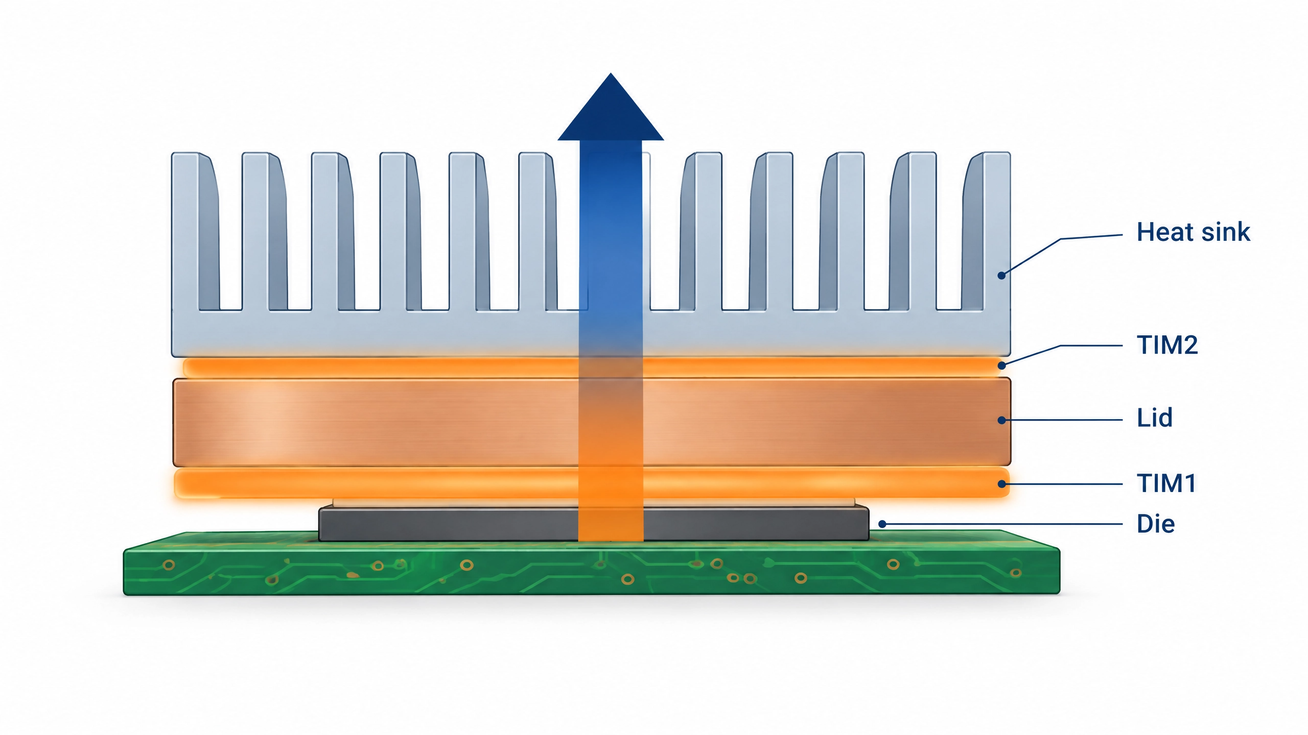
A metal thermal interface material (metal TIM) is a layer of indium, indium solder, or liquid gallium alloy that carries heat between a chip, lid, or heat sink by wetting both surfaces. Its payoff scales with heat flux: at 100 W/cm², every 0.01 °C·cm²/W of thermal impedance adds 1 °C (1.8 °F) of temperature across the interface. Therefore, reducing thermal impedance by 0.03 °C·cm²/W lowers the drop by 3 °C at 100 W/cm², but by only 0.3 °C at 10 W/cm².
Metal TIMs can address demanding high-heat-flux applications, but they also introduce metallurgical and reliability considerations. As heat generation in CPUs, GPUs, and AI accelerators rises, interface resistance has become a bottleneck (B. Liu et al., 2025). Three questions largely determine whether a metal TIM is appropriate: how much temperature drop the interface contributes, how it responds to thermal cycling, and how it interacts with the surfaces it contacts.
A Metal TIM Pays Off in Proportion to Heat Flux
Two quantities set the temperature difference across an interface. Thermal impedance, Z″, is the temperature difference across a layer per unit heat flux, including the layer’s bulk resistance and both contact resistances. It is reported here in °C·cm²/W (1 °C·cm²/W = 0.155 °C·in²/W). Average heat flux, q̄″, is in W/cm². The temperature difference, ΔT, is then:
Table 1 applies this relationship to published data. G. Liu et al. (2024) reported thermal resistances of 2.24 and 14.47 mm²·K/W for the same gallium–diamond TIM before and after 200 h of aging at 125 °C, and B. Liu et al. (2025) reported 2.8 mm²·K/W for a gallium–indium liquid-metal TIM. Table 1 converts these to thermal impedance at 1 mm²·K/W = 0.01 °C·cm²/W.
Table 1. Temperature drop across the interface, ΔT (°C), at three heat fluxes
| TIMs | Z″ (°C·cm²/W) | Temperature drop (°C) at 10 W/cm² |
Temperature drop (°C) at 50 W/cm² |
Temperature drop (°C) at 100 W/cm² |
|---|---|---|---|---|
| As-prepared gallium-diamond TIM | 0.0224 | 0.22 | 1.12 | 2.24 |
| Gallium-indium liquid metal | 0.028 | 0.28 | 1.40 | 2.80 |
| Illustrative polymer TIM | 0.100 (illustrative) | 1.00 | 5.00 | 10.00 |
| Aged gallium-diamond TIM at 125 °C for 200 h | 0.1447 | 1.45 | 7.24 | 14.47 |
The two studies used different fixtures, so the table shows scale rather than a ranking. The pattern is still clear. Against a 0.100 °C·cm²/W polymer interface, the liquid metal reduces the temperature difference by 0.72 °C at 10 W/cm² and by 7.2 °C at 100 W/cm². However, the aged interface ends up 4.47 °C worse than the polymer at 100 W/cm². A metal TIM earns its place when heat flux is high, and its thermal resistance stays low throughout the intended service life.
Ways to Put Metal in the Thermal Path
Table 2 compares four TIM families by physical state or assembly method, approximate thermal conductivity, and principal trade-offs. We take the thermal conductivity of indium from Brese et al. (2013), and the range for gallium alloys from Li et al. (2026).
Table 2. Metal TIM families at a glance
| Family | State/assembly | Approx. thermal conductivity | Main trade-off |
|---|---|---|---|
| Compressible indium foil | Solid foil compressed between mating surfaces | ~82 W/m·K | A. High conductivity and conformability B. Performance depends on pressure, surface flatness, and bond-line thickness |
| Indium solder TIM | Reflowed and bonded | ~82 W/m·K | A. Very low thermal resistance possible B. Requires compatible surfaces and careful management of thermomechanical strain |
| Liquid gallium alloys | Liquid during operation | ~25–30 W/m·K | A. Reduced solid-joint constraint due to higher wettability B. Reacts with common metals and needs containment, causing lower reliability |
| Polymer grease | Viscous polymer composite | Formulation-dependent | A. Simple to apply B. Higher thermal resistance |
Indium foil and indium solder: similar metal, different interface behavior
Compressible indium foil can function as a solid metallic TIM without forming a soldered joint. Under sufficient assembly pressure, soft indium plastically deforms to conform to surface irregularities, thereby reducing contact resistance. Its performance therefore depends strongly on contact pressure, surface finish, flatness, and foil thickness.
Indium solder TIMs, by contrast, are reflowed to form a bonded metallic interface. The resulting joint can provide very low thermal resistance. However, managing the coefficient-of-thermal-expansion (CTE) mismatch between the die and lid through bond-line thickness, lid material, metallization, and package design is critical.
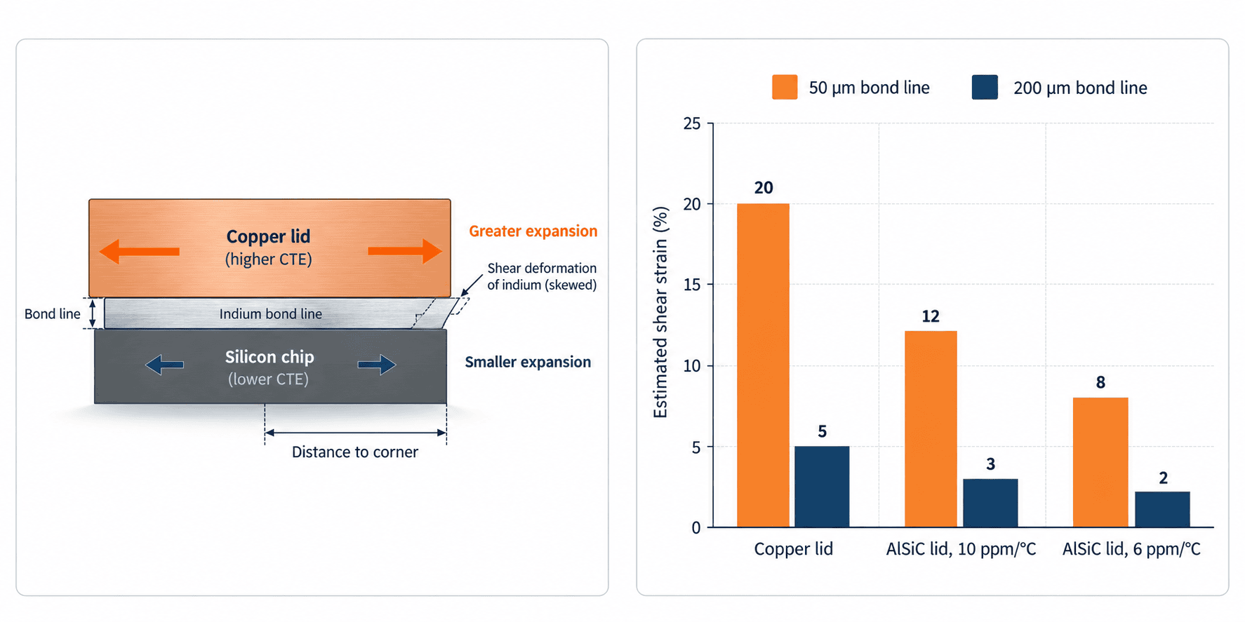
At a 50 μm bond line, indium’s bulk contribution to Z″ about 0.006 °C·cm²/W, so the surfaces matter more than the bulk. Reflowed indium can provide low interfacial resistance because it wets appropriately prepared surfaces (Brese et al., 2013). In the implementation described by Lofgreen et al. (2023), reflow involves flux and gold metallization, and once the indium solidifies, it forms a bonded connection between the die and the lid. During thermal cycling, this bonded joint experiences shear deformation because silicon and copper have substantially different CTEs. At room temperature (300 K), silicon has a CTE of approximately 2.53 ppm/°C, whereas copper has a CTE of approximately 16.58 ppm/°C (Bradley & Radebaugh, 2013).
Bond-line thickness and lid material set the strain
A first-order estimate of shear strain is obtained by multiplying the CTE mismatch by the temperature swing and the distance from the neutral point to the die corner, and then dividing by the bond-line thickness. For a 20 mm × 20 mm die attached to a copper lid and subjected to a 60 °C (108 °F) swing, that gives about 24% shear strain at a 50 μm bond line and 6% at 200 μm. This estimate does not account for warpage, plastic deformation, or creep; it therefore indicates only the approximate direction and magnitude of the effect, not fatigue life.
Two design levers follow. First, a thicker bond line lowers strain, which is why indium solder designs keep the TIM intentionally thick (Lofgreen et al., 2023). Second, a lid closer to silicon’s expansion helps too: aluminum-silicon carbide (AlSiC) composites measured CTE values of approximately 6 to 10 ppm/°C (H. S. Lee et al., 2000), reducing the estimated CTE-mismatch strain by 47% to 75%. Intel engineers have also studied the reliability of indium solder TIMs during temperature cycling as a function of bond-line thickness, die size, and lid metallization thickness (Deppisch et al., 2006).
Liquid gallium alloys: no joint strain, more chemistry
Gallium melts at 29.76 °C (85.6 °F), eutectic gallium-indium (EGaIn) at 15.7 °C (60.3 °F), and Galinstan at −19 °C (−2.2 °F) (Li et al., 2026). Because the alloy stays liquid, the die is mechanically decoupled from the lid. In the configuration described by Lofgreen et al. (2023), the liquid-metal TIM can also be implemented without gold or backside metallization (BSM).
The principal trade-off is chemical reactivity. In one aging study at 125 °C (257 °F), gallium formed CuGa₂ with copper; nickel plating slowed but did not stop intermetallic growth, and interface resistance rose from 2.24 to 14.47 mm²·K/W (0.0224 to 0.1447 °C·cm²/W) after 200 h (G. Liu et al., 2024). Nickel also reacts with liquid gallium to form Ga₇Ni₃, while gallium penetrates aluminum along its grain boundaries (D. Lee et al., 2021). Gallium alloys also conduct electricity; EGaIn has a conductivity of 3.4 × 10⁶ S/m (Li et al., 2026). Any leaked liquid metal poses a short-circuit risk. Barrier-layer selection, containment design, and aging performance at real operating temperatures matter as much as the initial thermal-resistance value.
Indium foil and liquid metal can work together
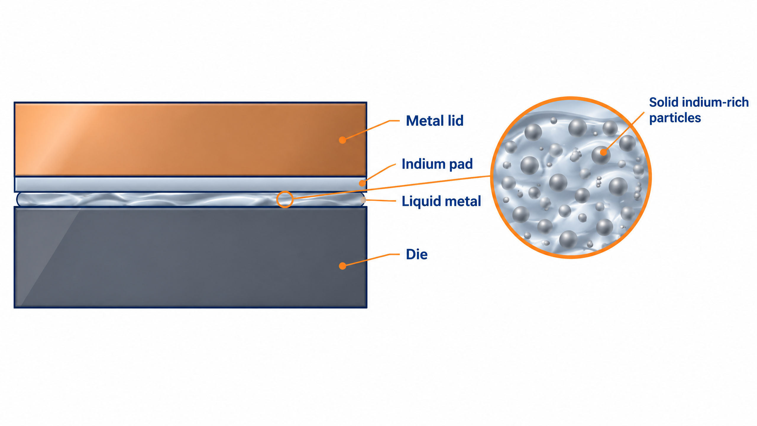
The two material families are not mutually exclusive. An Intel patent describes an indium pad, cold-rolled to a thickness below approximately 100 μm. A liquid gallium alloy wets preferentially, holding the liquid in place between die and lid without requiring metallization of the die. In another embodiment, gallium alloys react with the indium pad during assembly. At 20% to 30% indium by weight, the result contains solid indium-rich particles that the patent credits with preventing pump-out (Lofgreen et al., 2023). The patent’s stated goal is to make liquid metal TIMs more compatible with high-volume manufacturing.
Metal TIM Data Needs the Right Context
ASTM D5470-17(2024), a test method frequently cited on TIM datasheets, was developed for thermally conductive electrical-insulation materials (ASTM International, 2024). Indium and gallium conduct electricity, so a metal TIM value reported to D5470 uses an adapted test configuration, and the test conditions deserve scrutiny. At least four conditions can strongly influence the measured performance of a metal TIM: clamping pressure, dwell time under load, the surface finish and oxidation state of the contacting surfaces, and whether the sample was reflowed and, if so, onto what metallization.
Compressed indium foil is particularly sensitive to pressure. Indium yields at approximately 1.5 MPa and can therefore plastically flow into surface features under load. Both the resulting bond-line thickness and thermal resistance depend on the applied pressure. For example, on aluminum bars with a surface roughness of 1.6 μm, a 0.15 mm indium foil tested at 0.35 MPa reduced the interface resistance from 4.84 to 1.13 °C·cm²/W (C. Liu et al., 2026). Very low thermal-resistance values are also difficult to resolve experimentally. At a test heat flux of 10 W/cm², a specimen with an area-normalized resistance of 0.01 °C·cm²/W produces a temperature drop of only 0.1 °C.
Reliability data raises a similar point. JESD22-A104F.01 defines temperature cycling for components and solder interconnects (JEDEC Solid State Technology Association, 2023), but the qualification plan must also define the allowable change in Z″ after cycling. For gallium-based TIMs, that before-and-after comparison is what reveals aging drift, as with the gallium-diamond TIM in Table 1.
Where Each Option Fits
Table 3. Design conditions and the interface each favors
|
Design condition
|
Favored interface
|
Why
|
|
High heat flux, lidded package, metallized die
|
Indium solder or foil
|
High thermal conductivity; strain managed by bond line and lid design
|
|
High heat flux, low allowable die stress
|
Liquid gallium alloy on compatible, contained surfaces
|
No solid joint to strain
|
|
Aluminum in the path, or exposed circuitry nearby
|
Polymer TIM
|
Gallium attacks aluminum; liquid metal is electrically conductive
|
|
Relatively low heat flux
|
Phase change material or grease
|
The temperature reduction may be only a fraction of a kelvin
|
For lower-heat-flux interfaces, T-Global’s phase change materials and thermal greases cover the need without reflow or containment. When indium is selected, a CTE-matched AlSiC heat spreader can reduce thermomechanical strain in the joint. T-Global’s testing services can also support before-and-after thermal measurements.
T-Global USA is preparing indium foil and liquid metal TIM solutions for designs that have crossed into metal TIM territory. Engineers evaluating a high-heat-flux interface can share their requirements through Quote & Sample.
FAQs
What is a metal TIM?
A metal TIM is a thermal interface material made from indium, an indium-based solder, or a liquid gallium alloy, rather than a filled polymer. Depending on the material and assembly method, it reduces thermal contact resistance through plastic conformity, metallic bonding, wetting, or a combination of these mechanisms.
Is liquid metal better than indium?
Neither is better in general. Liquid metal can conform closely to mating surfaces without backside metallization and leaves no solid joint to strain, which suits bare die and stress-sensitive packages. Indium carries roughly three times the bulk thermal conductivity, stays where it is placed, and avoids the aluminum and short-circuit risks that come with a conductive liquid. The most meaningful comparison is therefore based on end-of-life thermal impedance measured under comparable test conditions, not two datasheets.
Can liquid metal touch an aluminum heat sink?
Not without a qualified barrier. Liquid gallium penetrates aluminum along its grain boundaries, opening channels from a few nanometers to several micrometers wide. Hence, the damage runs into the metal rather than sitting on the surface. Nickel plating slows the attack on copper but forms its own intermetallic with gallium, so any barrier needs aging data at the operating temperature.
How much temperature does interface resistance cost?
Multiply average heat flux in W/cm² by Z″ in °C·cm²/W:
ΔT = q̄″ × Z″
At 100 W/cm², each 1 mm²·K/W of interface resistance produces a 1 °C temperature drop. At 10 W/cm², the same resistance costs 0.1 °C. An interface at 0.028 °C·cm²/W therefore drops 1.4 °C at 50 W/cm² and 2.8 °C at 100 W/cm². Heat flux, not the material alone, determines whether the difference matters.
Do ASTM D5470 values apply to metal TIMs?
Yes, with one qualification. The standard was written for thermally conductive electrical-insulation materials, so labs adapt it for metals. Depending on the material and test temperature, the metal may wet the fixture, plastically deform under pressure, or undergo reflow. Clamping pressure, dwell time under load, surface finish, surface oxidation, metallization, and reflow conditions can all affect the result. The value applies only to the conditions tested. Identify those conditions before comparing results from different suppliers.
References
- ASTM International. (2024). Standard test method for thermal transmission properties of thermally conductive electrical insulation materials (ASTM D5470-17(2024)). https://store.astm.org/d5470-17.html
- Bradley, P. E., & Radebaugh, R. (2013). Properties of selected materials at cryogenic temperatures. National Institute of Standards and Technology. https://tsapps.nist.gov/publication/get_pdf.cfm?pub_id=913059
- Brese, N. E., Szocs, E., Schwager, F. J., Toben, M. P., & Bayes, M. W. (2013). Electrochemically deposited indium composites (U.S. Patent No. 8,585,885 B2). U.S. Patent and Trademark Office. https://image-ppubs.uspto.gov/dirsearch-public/print/downloadPdf/8585885
- Deppisch, C., Fitzgerald, T., Raman, A., Hua, F., Zhang, C., Liu, P., & Miller, M. (2006). The material optimization and reliability characterization of an indium-solder thermal interface material for CPU packaging. JOM, 58(6), 67–74. https://doi.org/10.1007/s11837-006-0186-6
- JEDEC Solid State Technology Association. (2023). Temperature cycling (JESD22-A104F.01). JEDEC.
- Lee, D., Kim, C.-L., & Sohn, Y. (2021). Formation and growth of intermetallic compounds during reactions between liquid gallium and solid nickel. Materials, 14(19), 5694. https://doi.org/10.3390/ma14195694
- Lee, H. S., Jeon, K. Y., Kim, H. Y., & Hong, S. H. (2000). Fabrication process and thermal properties of SiCp/Al metal matrix composites for electronic packaging applications. Journal of Materials Science, 35(24), 6231–6236. https://doi.org/10.1023/A:1026749831726
- Li, Z., Han, X., Guo, X., Ma, L., Sun, J., Wen, Y., & Guo, Y. (2026). Gallium-based liquid metals: From properties to applications. Nanomaterials, 16(8), 471. https://doi.org/10.3390/nano16080471
- Liu, B., Gao, W., Duan, L., Li, Q., Gong, S., Li, R., & Zhang, J. (2025). Performance analysis of gallium-based liquid metal as thermal interface material for chip heat dissipation. International Journal of Thermal Sciences, 218, 110121. https://doi.org/10.1016/j.ijthermalsci.2025.110121
- Liu, C., Qin, J., Bai, Y., Wang, J., & Li, Y. (2026). Study on thermal resistance characteristics and thermal validation of indium foil-filled thermal interfaces for space cameras. Applied Sciences, 16(9), 4411. https://doi.org/10.3390/app16094411
- Liu, G., Zhang, Y., Ma, C., Tang, Q., Li, H., Chen, S., & Shen, J. (2024). Corrosion inhibition of Ga-based thermal interface materials with Ni coating on Cu substrate. Surface and Coatings Technology, 493, 131286. https://doi.org/10.1016/j.surfcoat.2024.131286
- Lofgreen, K., Chiu, C.-P., Petrini, J., Cetegen, E., Gebrehiwot, B., & Eid, F. (2023). Liquid metal TIM with STIM-like performance with no BSM and BGA compatible (U.S. Patent No. 11,551,994 B2). U.S. Patent and Trademark Office. https://patents.google.com/patent/US11551994