Contents
- Where Heat Actually Concentrates on a Small Satellite
- Passive vs. Active Thermal Control Systems
- The Small Satellite Thermal Materials Toolbox
- FAQs
- The Takeaway: Why Thermal Design Decides Mission Success
- References
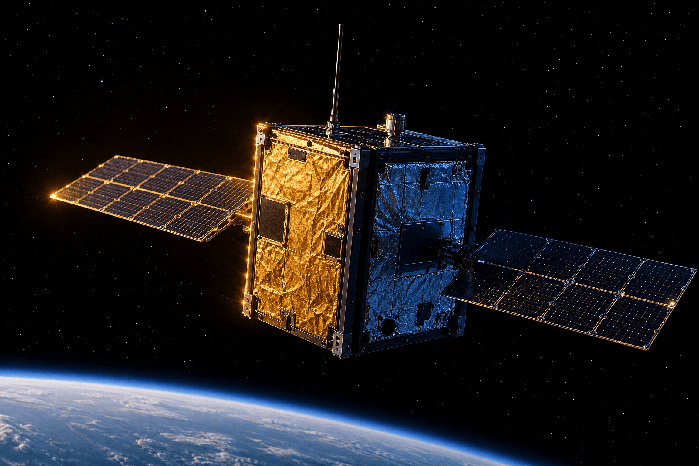
Small satellite thermal management keeps batteries, electronics, and payloads within safe operating temperatures through swings from −160°C to +120°C, as satellites cross from sunlight to darkness every 45 minutes, 16 times a day (Thermal Control, 2026; Thermal Control of CubeSat Electronics Using Thermoelectrics, 2020). With no air for convective cooling, engineers rely on conduction and radiation: passive phase change materials (PCM) and silicone-free thermal interface materials (TIMs) for most subsystems, active thermoelectric coolers (TECs) only where passive design falls short.
Small satellites feel this more acutely: less structure and surface area than the larger spacecraft they descended from, yet often higher power density from packing similar hardware into a smaller footprint (Center, 2020). It’s one of the first design constraints, not a checkbox after the fact.
💡 Read more: Recent market activity underscores the pace of small-satellite deployment: in July 2026, the Space Development Agency announced $1.75 billion in awards for 36 additional Tracking Layer satellites, with delivery aimed for launch by the end of 2028. Full announcement.
Where Heat Actually Concentrates on a Small Satellite
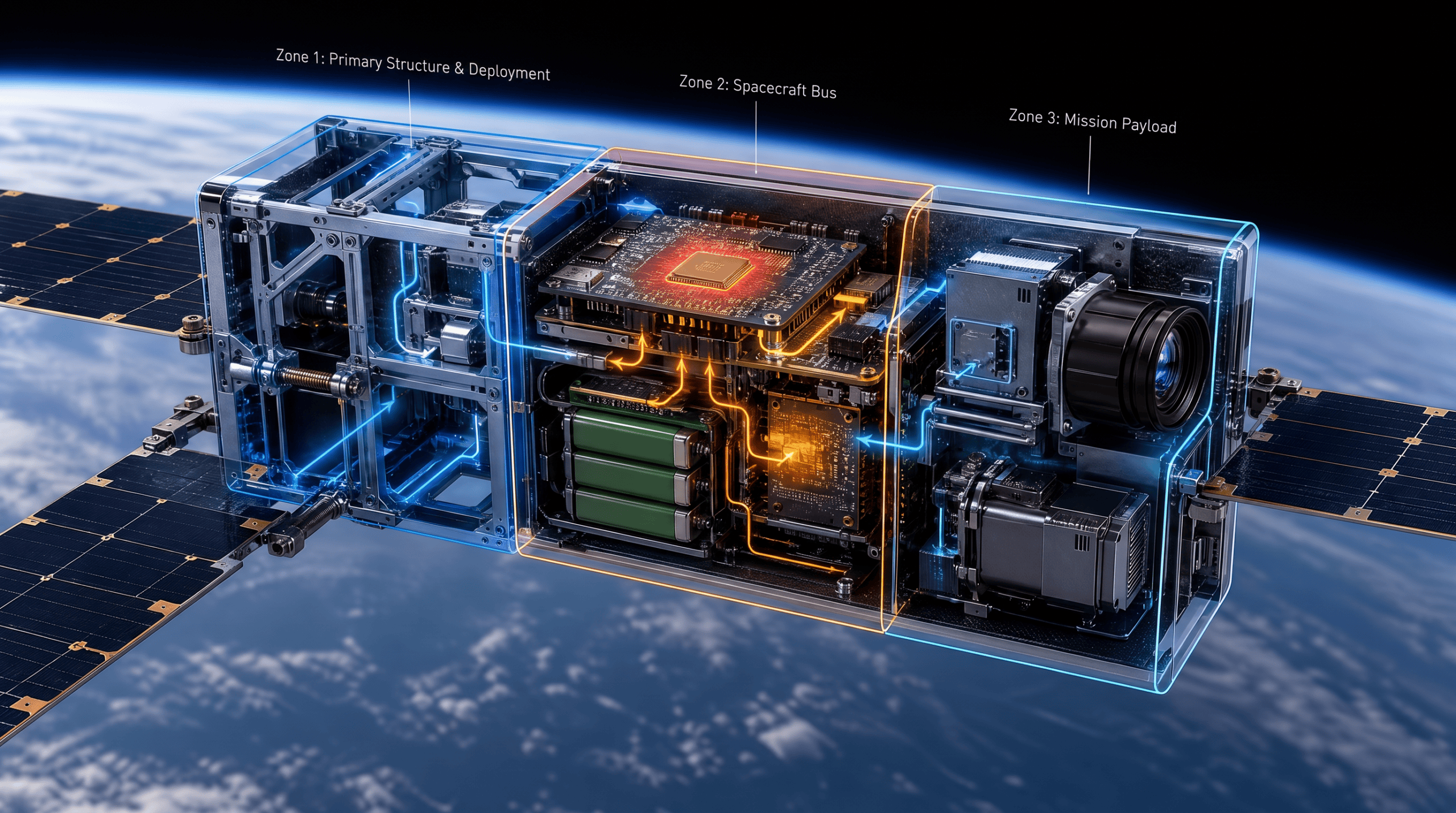
Components a few centimeters apart can face entirely different thermal environments depending on orientation and mounting, which is why no single thermal fix covers the whole vehicle: each subsystem fails differently, at a different temperature and on a different timescale.
Batteries: Protecting a Narrow Thermal Window
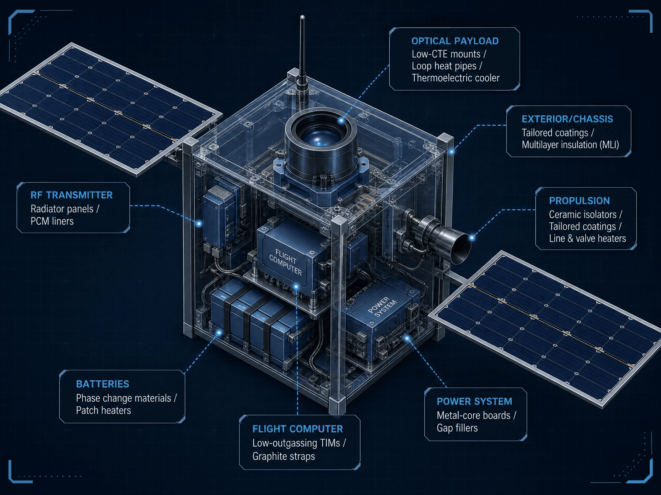
Batteries have the least margin of any subsystem: healthy cycle life needs cells held between roughly 0°C and 20°C, with degradation below freezing and thermal runaway risk above it (Hoffpauir, 2019). Flown 1U CubeSats including Compass-1, MASAT-1, and OUTFI-1 each needed a dedicated battery heater to survive eclipse without degrading (7.0 Thermal Control, 2026).
Most designs pair a phase change material (PCM), a wax or paraffin matrix absorbing latent heat while charging and releasing it through eclipse, with low-outgassing patch heaters and standoffs isolating the pack from the chassis. Melting point, conductivity, and outgassing are the main PCM selection criteria; T-Global’s TG-PCM095 is one high-conductivity formulation built for a CubeSat battery bay.
On-Board Computer & Power System: Managing Concentrated Heat Flux
The flight computer and power system face concentrated heat flux, not a narrow tolerance: processor junctions are rated to 85°C, and EPS components generate steady waste heat from voltage regulation losses. The fix is spreading, not buffering: copper-via or metal-core boards move heat laterally, and silicone-free thermal interface materials close the gaps without outgassing risk.
Optical Payloads: Precision Thermal Stability for Imaging
Optical payloads care about gradients, not absolute temperature: a small bench difference throws a telescope out of focus, and a warmed sensor adds noise. Thermoelectric coolers (TECs), solid-state Peltier devices, pump heat off CMOS or CCD sensors to a stable set point. But a TEC only moves heat: its rejected load, 8 to 20 W on SWIFT XRT, still needs a path to space, and on a satellite cycling sun to eclipse every 90 minutes, that spikes the radiator when the TEC runs and over-cools it when idle (Choi, 2000).
PCM buffers this the way it buffers the battery bay: mounted between the TEC’s hot side and the radiator, it melts sun-facing, absorbing the TEC’s heat and solar load, then refreezes in eclipse and releases that heat through the radiator instead of the panel taking the full swing, confirmed in vacuum-tested PCM-radiator assemblies (Hartsfield et al., 2020) and an early patent on sun-side panels that melt in sunlight and radiate stored heat in shadow (Klett & Burchell, 2004). The PCM itself isn’t the radiating surface; it decouples when heat is generated from when the radiator must reject it.
RF Transmitters: Taming Transient Heat Spikes
RF transmitters face a timing problem, not a magnitude one: amplifiers spike during short 10 to 15 minute downlink windows, and efficiency drops as temperature climbs, right when the mission needs it most. Radiator panels handle the steady load; small PCM reservoirs next to the amplifier absorb each burst’s spike so the structure doesn’t react instantly.
Propulsion & Chassis: Surviving the Full Orbital Swing
Propulsion and the external chassis take the full brunt of the swing described earlier: propellant lines risk freezing between burns, thruster nozzles run hot during firing, and exterior panels cycle through the full −100°C to +100°C range every orbit. Zone-controlled patch heaters prevent freezing without heating the whole system; ceramic isolators block conduction where it isn’t wanted.
Passive vs. Active Thermal Control Systems
Passive materials are the default given how scarce power is on a small satellite. Active systems, TECs and patch heaters, are reserved for subsystems that can’t tolerate drift; TECs in particular are often assumed to be cooling-only, but their real value is bidirectional, precise temperature control, pushing heat either direction to hold a component at a steady target, such as 0°C, rather than just pulling heat out (Guo et al., 2020).
Passive vs. Active: A Subsystem Summary Matrix
| Subsystem | Primary Risk | Passive Approach | Active Approach |
|---|---|---|---|
| Batteries | Freezing / thermal runaway | PCMs | Patch heaters |
| Flight computer Power system |
Localized heat flux, continuous regulator losses | Low-outgassing TIMs, graphite straps, metal-core boards | — |
| Optical payload | Focus drift, sensor noise | Low-CTE mounts, loop heat pipes, PCM-buffered TEC heat rejection | TECs |
| RF transmitter | Transient heat spikes | Radiator panels, PCM liners | — |
| Propulsion | Freezing lines, plume heat | Ceramic isolators, tailored coatings | Line and valve heaters |
The Small Satellite Thermal Materials Toolbox
Core Material Categories
In practice, the whole design comes down to a compact set of material families:
- Graphite conductors: spread heat with almost no added mass.
- Silicone-free pads and gap fillers: close conduction paths near sensitive optics.
- Phase change materials (PCM): buffer transient heat loads.
- AlSiC and indium: handle the most demanding high-conductivity joints.
- TECs: bidirectional, precise temperature control, not just cooling, for the few spots passive design won’t hold tolerance.
Choosing a Thermal Materials Partner
Few suppliers carry that entire range under one roof. T-Global USA does: thermal pads, gap fillers, PCM, graphite and graphene, AlSiC, and TEC modules all sit in the same catalog, backed by in-house simulation and testing that validates a material choice against a thermal model before it reaches hardware.
FAQs
Can thermal materials be customized for a specific mission or component?
Often: melting point, conductivity, and form factor can frequently be tuned to a specific thermal cycle, component geometry, or mounting constraint rather than chosen from a standard catalog listing. T-Global’s in-house simulation and testing can help evaluate a proposed formulation against your thermal model before you commit to hardware.
How much mass or volume does thermal management typically add to a subsystem?
Passive materials generally add only grams, not the volume penalty of a full active system: a PCM liner in a battery bay adds relatively little compared to a TEC, which brings its own power draw and a dedicated heat-rejection path on top of the unit itself. That’s a large part of why passive stays the default, with active temperature control reserved for subsystems, like optical payloads, that can’t tolerate drift.
What information helps identify the right thermal material for a subsystem?
The subsystem’s operating temperature range and duty cycle, the specific failure mode you’re protecting against (freezing, thermal runaway, focus drift, etc.), and any mass or outgassing constraints. That’s usually enough for an initial passive or active recommendation, which a thermal model can then refine further.
The Takeaway: Why Thermal Design Decides Mission Success
Thermal engineering keeps everything else on the spec sheet working once the spacecraft is somewhere no one can walk up and fix it. The materials and strategies here are well understood; the real work is matching the right one to the right hazard early, so it shapes the structural design instead of getting squeezed into whatever space is left over.
Every mission’s thermal budget is different, so getting that match right takes the right partner: T-Global USA’s team can help identify the correct solution for your subsystem, validate it against your thermal model, and get a sample into your hands fast.
➡️ See T-Global USA’s Ultimate Guide to Thermal Management Solutions to compare passive and active cooling strategies, evaluate thermal interface materials, and find the right approach for high-reliability avionics.
References
- (2026). Thermal Control. NASA Small Spacecraft Technology State-of-the-Art Report. https://www.nasa.gov/smallsat-institute/sst-soa/thermal-control/
- (2020). Thermal Control of CubeSat Electronics Using Thermoelectrics. MDPI Electronics 13(11). https://doi.org/10.3390/electronics13116480
- Center, N. G. (January 1, 2020). CubeSat Form Factor Thermal Control Louvers. NASA. https://www.nasa.gov/content/cubesat-form-factor-thermal-control-louvers
- Hoffpauir, D. (September 4, 2019). Calorimetry of Lithium-ion Cells During Thermal Runaway. NASA. https://www.nasa.gov/centers-and-facilities/nesc/calorimetry-of-lithium-ion-cells-during-thermal-runaway/
- Choi, M. K. (2000). Thermal Considerations of SWIFT XRT Radiator at −35°C or Colder in Low Earth Orbit. AIAA Paper 2000-2906, 35th Intersociety Energy Conversion Engineering Conference. NASA Technical Reports Server. https://ntrs.nasa.gov/api/citations/20000070727/downloads/20000070727.pdf
- Guo, D., Sheng, Q., Dou, X., Wang, Z., Xie, L., & Yang, B. (2020). Application of Thermoelectric Cooler in Temperature Control System of Space Science Experiment. Applied Thermal Engineering, 168, 114888. https://www.sciencedirect.com/science/article/abs/pii/S1359431119339705
- Hartsfield, C. R., Shelton, T. E., Palmer, B. O., & O’Hara, R. (2020). All-Metallic Phase Change Thermal Management Systems for Transient Spacecraft Loads. Journal of Aerospace Engineering, 33(4). https://doi.org/10.1061/(ASCE)AS.1943-5525.0001150
- Klett, J. W., & Burchell, T. D. (2004). Pitch-Based Carbon Foam Heat Sink With Phase Change Material. U.S. Patent No. 6,780,505 B2. Oak Ridge National Laboratory / U.S. Department of Energy. https://patents.google.com/patent/US6780505
- Space Development Agency, Proliferated Warfighter Space Architecture — Tranche 1 Factsheet: sda.mil. Cited here as evidence of an active, large-scale small-satellite constellation program; SDA does not publish subsystem-level thermal engineering specifications publicly.