Contents
- Why High-Power AI Racks Change the Thermal Interface Design
- Where Liquid Cooling Meets the GPU Package
- How Liquid Cooling Is Changing Interface Requirements
- Direct-Die and Direct-to-Silicon Cooling
- Designing the Interface and the Thermal Module Together
- Matching Interface Materials to Their Position in the Stack
- FAQs
- References
AI server racks now demand far more from power delivery and cooling: NVIDIA’s MGX 1.2 rack architecture for Vera Rubin supports deployments of up to 250 kW per rack (NVIDIA, 2026).
At the GPU level, heat reaches the cold plate only after crossing the package and its thermal interfaces. In a lidded GPU, TIM2 connects the integrated heat spreader (IHS) to the cold plate, and its performance depends on installed bond line thickness, contact pressure, the mating surfaces, and how the material behaves over its service life.
These developments make the GPU interface a shared concern for package, cooling-module, and server teams. Higher power, warmer coolant, and evolving cooling architectures are changing what those interfaces must deliver.
Why High-Power AI Racks Change the Thermal Interface Design
Higher rack power, warmer coolant, and broader liquid-cooling coverage are changing the conditions at GPU interfaces. Five developments show how these system-level changes reach the package and cold plate.
More heat through every interface
Some AI chips now have thermal design powers (TDPs) above 1 kW (TrendForce, 2026). Meanwhile, 800 VDC distribution is designed to scale racks from 100 kW to over 1 MW (Blake et al., 2025), and OCP has published a white paper on DC distribution architectures (Kelly et al., 2026). At the same interface area, increasing heat flow from 300 W to 1,000 W more than triples the average heat flux. At a fixed impedance, the temperature drop across the interface rises proportionally, so a TIM that once fit its share of the budget may no longer do.
Warmer coolant, smaller budget
NVIDIA’s reference layout supplies 41 °C facility water to CDUs and 45 °C coolant to racks (Bhargava et al., 2026). For interface budgeting, use the coolant temperature entering the relevant cold plate, including any upstream heating. At an unchanged junction limit, a 10 °C warmer inlet leaves 10 °C less temperature budget.
Better cold plates raise the TIM’s share
In TSMC’s reported ECTC 2026 tests with 40 °C deionized water, lidded and lidless cold-plate assemblies showed diminishing returns above 4 L/min as the TIM became the limiting resistance (Ahmad et al., 2026). At fixed heat load and TIM impedance, reducing cold-plate resistance increases the TIM’s share of the remaining temperature rise.
More components on the liquid loop
Liquid cooling is extending to network cards, power boards, and optical modules (TrendForce, 2026). NVIDIA’s MGX 1.2 includes a liquid-cooled 5,000 A busbar, while Meta’s IcePack applies liquid cooling to networking (NVIDIA, 2026). Where multiple components contact a shared cold plate, their gap tolerances and interface loads become part of the module design.
Faster service, new rework demands
Vera Rubin’s modular, hoseless trays cut assembly time from nearly 2 hours to about 5 minutes (Bhargava et al., 2026), with cold plates attached at module level right after board assembly (Chu et al., 2026). Where service separates a cold plate from its package, at the module line or a service depot, TIM2 and nearby gap fillers must survive rework or be easy to replace.
Where Liquid Cooling Meets the GPU Package
For a lidded GPU package with a separate cold plate, the simplified main heat path is:
GPU junction → silicon → TIM1 → integrated heat spreader (IHS) → TIM2 → cold plate → coolant
A lumped thermal-resistance model suffices for an initial temperature budget. Still, lateral heat spreading, nonuniform power, and logic–memory thermal coupling may require a spatial model to predict local junction temperatures.
Budget with the application’s actual power and power distribution: TDP is only a design reference, and workload variation and transient response need separate evaluation when they affect the temperature limit.
Figure 1. Interface Positions in a Fanless, Liquid-Cooled GPU Tray
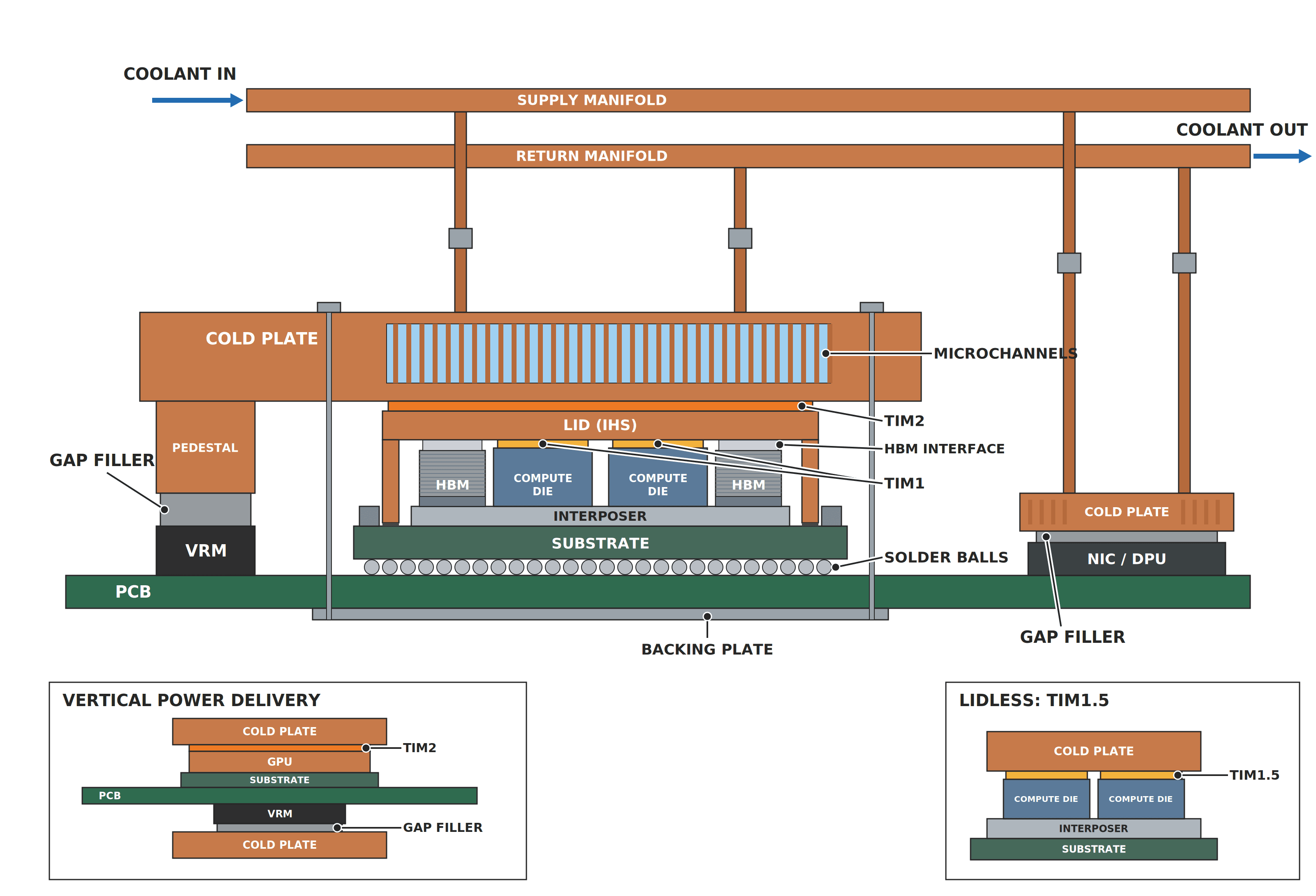
Note. Representative schematic, not to scale. Based on Pinkus et al. (2026), Chu et al. (2026), and Choi et al. (2025).
TIM1 usually comes with the GPU package, so server and cooling-module designers specify TIM2 and the neighboring interfaces within the package supplier’s limits on mounting load, surface condition, geometry, and approved materials. Their practical task is to define the installed interface conditions and verify performance within them.
How Liquid Cooling Is Changing Interface Requirements
Thermal Impedance and Heat Flow
An interface’s area-normalized thermal impedance (°C·cm²/W) includes the TIM layer and both contacts (Prasher, 2006). Compare it at the relevant BLT, pressure, temperature, and surface conditions. At a given impedance, higher heat flux produces a larger temperature drop. TIM1 generally carries heat over a smaller area than TIM2, while local peaks can remain above the dies. Thermal conductivity alone does not describe the installed joint (see What is heat flux? Why W/cm² tells you more than total watts).
Figure 2. Heat Flux at the TIM1 and TIM2 Interfaces
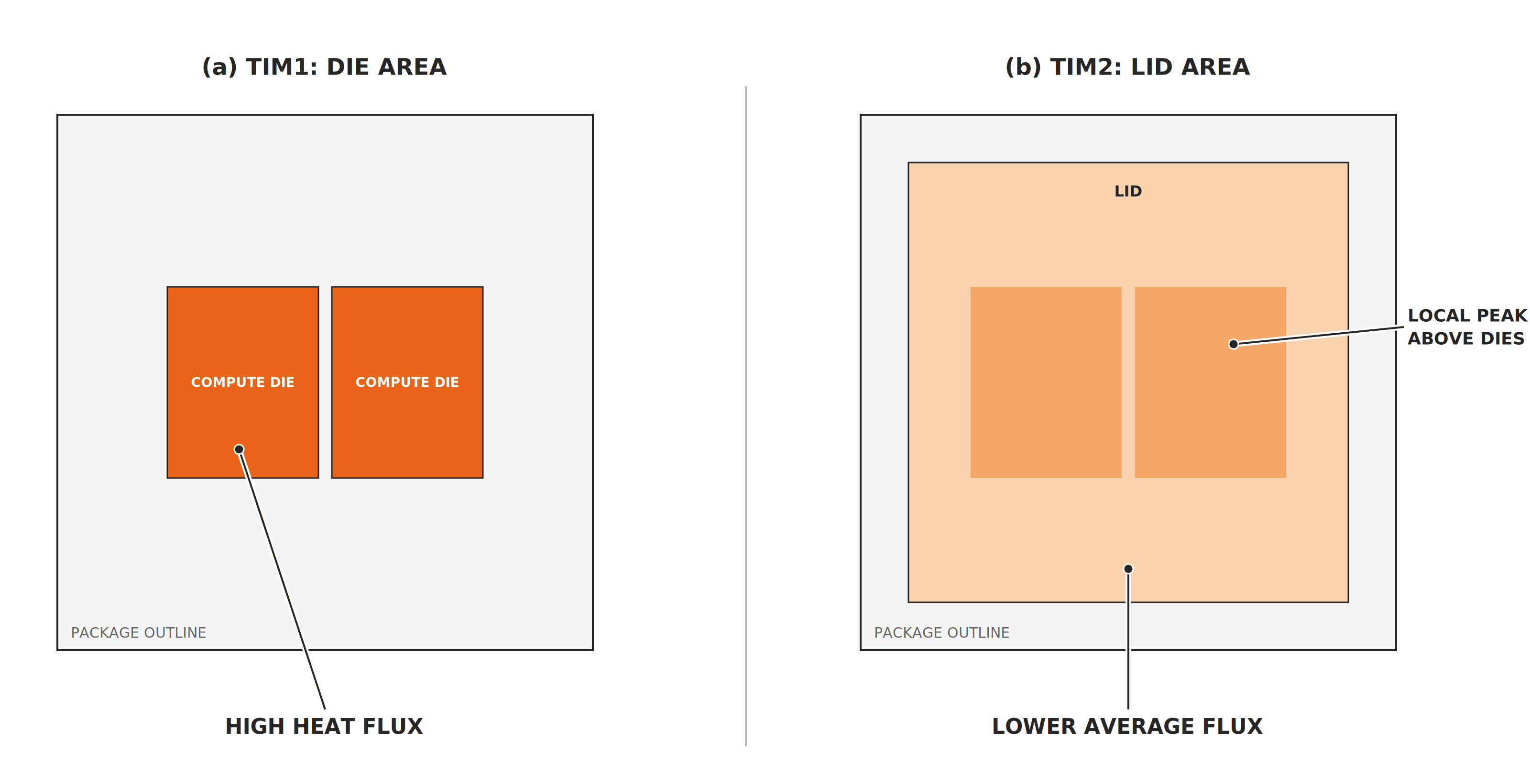
Note. For the same upward heat flow, the larger TIM2 area lowers average heat flux, while local peaks remain above the dies. Other package heat paths are omitted. Shading indicates relative heat flux. Schematic, not to scale.
In a uniform 1,000 W test over 75 × 75 mm, a copper diamond-pin cold plate achieved a 7.6 °C heater-surface-to-inlet rise at 4.15 kPa pressure drop. The TIM contribution, estimated from its rated resistance, was about 1.2 °C. At this flux, another 0.1 °C·cm²/W adds about 1.8 °C (Pinkus et al., 2026). Predicting GPU junction temperature also requires the package thermal path and power map.
Bond Line Thickness and Mounting Pressure
Within the package supplier’s allowable load range, increasing pressure can improve contact and reduce BLT. The resulting pressure distribution also depends on cold-plate stiffness, mounting geometry, and the forces carried by neighboring interfaces.
The problem grows when one cold plate spans several devices: the GPU lid may need high pressure for a thin TIM2 bond line, while gap fillers on VRMs, memory, and retimers push back against the same plate. Depending on their area, compression, and stiffness, those fillers can take clamping load away from the GPU interface.
NVIDIA’s rack-level 800 VDC distribution (Blake et al., 2025) and processor-level vertical power delivery (Choi et al., 2025) operate at different design levels. For TIM design, the relevant question is which devices share a cold plate and how their reaction forces affect GPU contact pressure, including designs with a second cold plate below the board (Wiwynn, 2026).
Figure 3. Clamping Force with Lateral and Vertical Power Delivery
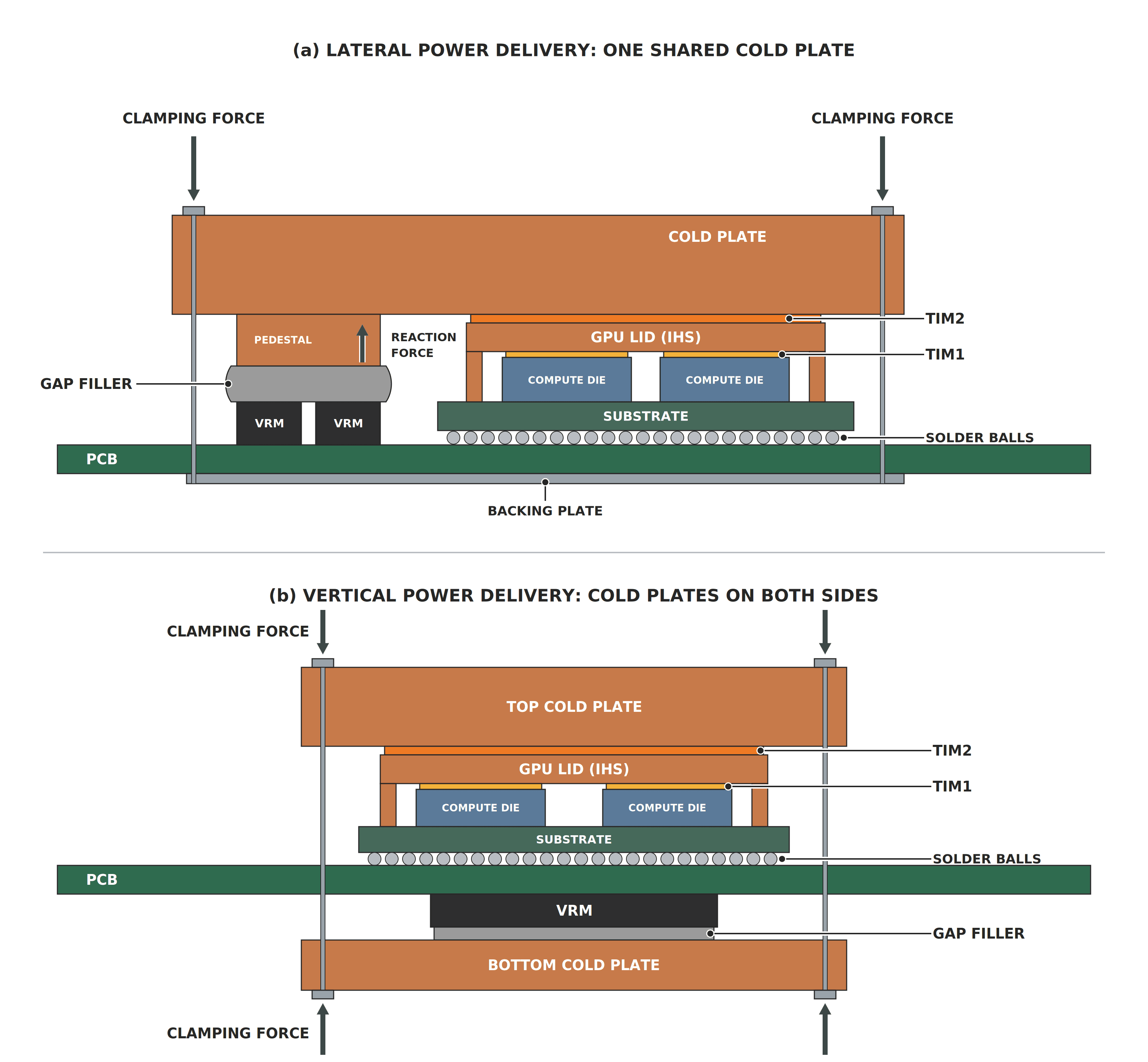
Note. (a) One cold plate shared by the GPU and VRMs; (b) VRM beneath the GPU with a second cold plate below the board. Arrows indicate mechanical force, not heat flow. Schematic, not to scale. Based on Choi et al. (2025) and Wiwynn (2026).
Warpage and Tolerance Stack
A real GPU-to-cold plate interface is rarely flat: component height, PCB warpage, lid and plate flatness, pedestal tolerance, thermal expansion, and load deformation all vary pressure and bond line thickness locally. Intel Foundry described a disaggregated IHS approach that could reduce package warpage by up to 30%, while earlier stiffener attachment reduced TIM1 voids by 25% (Intel Foundry, 2025). The TIM2 joint still requires validation under the assembled geometry.
Figure 4. Effect of Lid Warpage on the TIM2 Bond Line
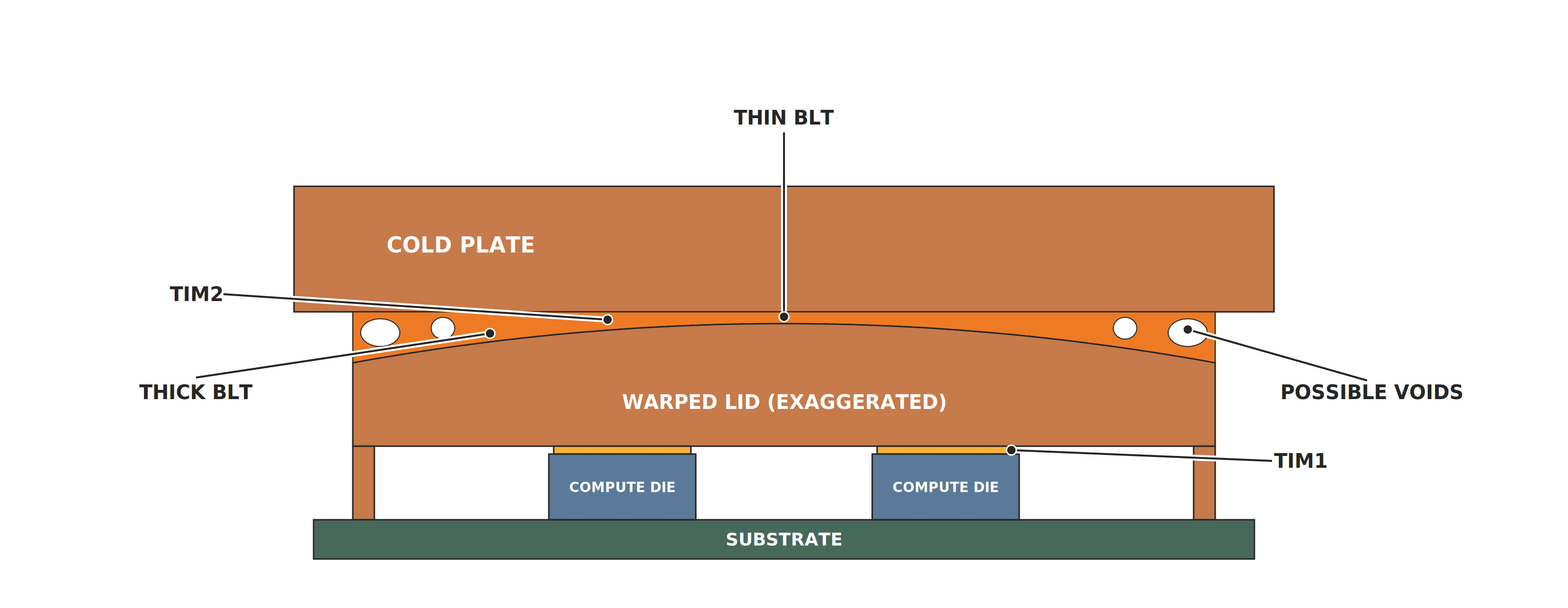
Note. BLT = bond line thickness. Voids mark possible loss of contact. Warpage is exaggerated for clarity. Schematic, not to scale. Based on Kulkarni et al. (2026).
Gap Fillers and Tolerance Accommodation
Select against both ends of the gap range: maintain contact at the largest gap without exceeding component load limits at the smallest. Pads provide controlled placement; curable gels add a curing step, while non-curing putties remain paste-like. Dispensing consistency, reaction force, and rework requirements also affect the choice.
Reliability, Aging, and Reworkability
AI training can swing GPU power sharply: tens of thousands of GPUs may ramp up or down together, moving data center demand by tens of megawatts (Llama Team, AI @ Meta, 2024). How much of that becomes temperature cycling at an interface depends on the assembly’s thermal response, so qualification needs representative temperature ranges, ramp rates, and dwell times.
In power-cycling tests, mating-surface curvature strongly affected how grease degraded, and a thinner bond line at the center did not guarantee better stability (Kulkarni et al., 2026).
Figure 5. TIM2 Coverage Before and After Power Cycling
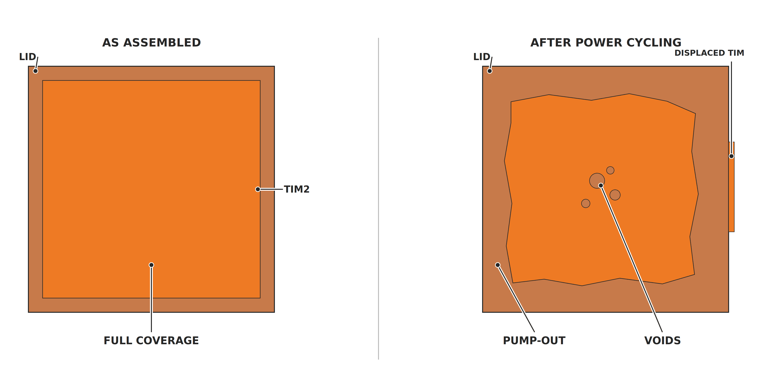
Note. Top-down view of the lid surface showing possible grease migration and voiding after power cycling. Schematic, not to scale; the coverage shown is illustrative rather than measured. Based on Kulkarni et al. (2026).
These findings make long-term interface stability a material-selection priority alongside initial impedance. For phase change films and other TIMs, the relevant performance is what the assembled module retains through operation and service.
Direct-Die and Direct-to-Silicon Cooling
Lidless cold plates retain one compliant TIM between silicon and plate, called TIM1.5 here. In a TSMC test vehicle using CoWoS-R, the RDL-interposer variant of CoWoS, removing the lid increased reported dissipation from 1.9–2.3 kW to 2.5–3.0 kW at 1–2 L/min with 40 °C water (Ahmad et al., 2026). Die loading and thermal-expansion mismatch remain design constraints (Pinkus et al., 2026).
TSMC’s direct-to-silicon micropillar variant dissipated 5.3 kW at 8 L/min, with coolant contacting silicon directly. Its seals had to accommodate package warpage and thermal-expansion mismatch (Ahmad et al., 2026).
Microsoft’s GH200 design used microchannels etched into GPU silicon. At 1 L/min, reported GPU junction-to-inlet thermal resistance fell by 51–60% across tested workloads compared with conventional cold-plate cooling. HBM improved by 27–37% while retaining a cold plate and TIM (Ahmad et al., 2026). GPU and HBM thermal paths therefore still require separate evaluation.
Designing the Interface and the Thermal Module Together
An interface performs only as well as the hardware it clamps to: a TIM qualified on flat fixtures can underperform on a plate with different stiffness, flatness, or pedestal heights, so it must be co-designed with the surrounding hardware rather than treated as a passive filler.
T-Global supports custom thermal module design, simulation, and manufacturing. For liquid-cooled GPU assemblies, co-design should address cold-plate flatness and pedestal heights, TIM2 BLT, gap-filler reaction forces, and mounting load. Evaluating these conditions together helps connect material selection to the interface performance the hardware can maintain.
Matching Interface Materials to Their Position in the Stack
Interface priorities vary across the stack as cooling architectures evolve.
- GPU lid (TIM2). Material choice is driven by installed impedance, aging stability, and serviceability. Phase change materials and greases are candidates; metal options add compatibility and process requirements.
- Direct-die interface. Die loading, coplanarity, and surface compatibility constrain material choice. Package-approved TIMs are essential; liquid metal also requires compatible surfaces and effective containment.
- Power stages. Select pads, gels, and putties for gap range, allowable reaction force, and electrical requirements, including dielectric isolation where needed.
- Board-level memory, NICs, and retimers. Soft pads, gels, and putties address different gap conditions, component load limits, and manufacturing and service requirements.
Where electrical insulation is required, dielectric performance at the installed thickness matters; creepage and clearance remain assembly-level requirements.
Select the interface for the performance the assembly can maintain through manufacturing, operation, and service. For an application review, provide the heat-source size and power map, cold-plate inlet temperature and flow, mounting-load limits, gap range, surface finish, and service requirements. These inputs help T-Global discuss suitable interface materials, custom thermal modules, and representative sample evaluation.
FAQs
Does direct liquid cooling get rid of the need for gap fillers?
No. As liquid cooling extends to NICs, power boards, and optical modules, additional components can require interfaces to shared or separate cold plates. This can increase the need for gap fillers across a tray.
Will 800 VDC power distribution make GPU trays easier to cool?
Not by itself. 800 VDC cuts conversion steps and losses in the facility power chain (Blake et al., 2025), but DC/DC stages inside the rack still step power down to GPU core voltage, and tray cooling depends on where those losses land and how the converters are placed.
What about indium solder or liquid metal TIMs?
Indium solder, compressed foil, and liquid metal offer different assembly and service trade-offs (see our metal TIM guide). Solder requires compatible surface metallization and controlled bonding; compressed indium foil avoids reflow but still depends on contact load and surface geometry.
Early Rubin reports described liquid-metal TIM2 with gold-plated mating surfaces (Chu et al., 2026). Later reporting linked a heat-spreader redesign to substrate warpage (TrendForce, 2026). SPIL’s liquid-metal composites also show why formulation matters: both had lower thermal resistance than a 4 W/m·K silicone TIM, while carbon-fiber and silicone-matrix variants retained 95% and 75% coverage after 1,000 hours at 150 °C (Ahmad et al., 2026).
Liquid metal is an option for compatible bare-die designs, with electrical conductivity and containment remaining key constraints. For lower-flux TIM2, a removable phase change material is often a practical starting point, if it meets tray requirements.
References
- Ahmad, A., TC, Wong, G., & Patel, D. (2026, July 2). EMIB-T roadmap, custom HBM, HBM4 packaging challenges, microfluidic cooling, photonic interconnects, and more. SemiAnalysis. https://newsletter.semianalysis.com/p/ectc2026
- Bhargava, R., Allison, T., & Petty, H. (2026, March 16). NVIDIA Vera Rubin POD: Seven chips, five rack-scale systems, one AI supercomputer. NVIDIA Technical Blog. https://developer.nvidia.com/blog/nvidia-vera-rubin-pod-seven-chips-five-rack-scale-systems-one-ai-supercomputer/
- Blake, M., Hsu, M., Goldwasser, I., Petty, H., & Huntington, J. (2025, May 20). NVIDIA 800 VDC architecture will power the next generation of AI factories. NVIDIA Technical Blog. https://developer.nvidia.com/blog/nvidia-800-v-hvdc-architecture-will-power-the-next-generation-of-ai-factories/
- Choi, M., Krishnakumar, S., Rahimzadeh Khorasani, R., Swaminathan, M., Partin-Vaisband, I., & Kumar, S. (2025). Substrate-embedded microfluidic cooling of distributed vertical power delivery architectures for high-performance computing processors. IEEE Transactions on Components, Packaging and Manufacturing Technology, 15(9), 1912–1920. https://doi.org/10.1109/TCPMT.2025.3544105
- Chu, W., Patel, D., Nishball, D., et al. (2026, February 25). Vera Rubin – Extreme co-design: An evolution from Grace Blackwell Oberon. SemiAnalysis. https://newsletter.semianalysis.com/p/vera-rubin-extreme-co-design-an-evolution
- Intel Foundry. (2025). Intel Foundry research simplifies heat spreader assembly to enable extra-large advanced packages. Intel Community [Blog post]. https://community.intel.com/t5/Blogs/Intel-Foundry/Systems-Foundry-for-the-AI-Era/Intel-Foundry-Research-Simplifies-Heat-Spreader-Assembly-to/post/1725240
- Kelly, J., Grossner, C., & Ball, Z. (2026, October 12). Realizing the OCP open data center ecosystem vision. Open Compute Project. https://www.opencompute.org/news/realizing-the-ocp-open-data-center-ecosystem-vision/
- Kulkarni, R. V., Gronowski, N. P., & Marconnet, A. M. (2026). Experimental characterization of thermal grease degradation between warped mating surfaces in power-cycled assemblies. Applied Thermal Engineering, 289, Article 129742. https://doi.org/10.1016/j.applthermaleng.2026.129742
- Llama Team, AI @ Meta. (2024). The Llama 3 herd of models (arXiv:2407.21783). arXiv. https://doi.org/10.48550/arXiv.2407.21783
- NVIDIA. (2026, October 12). OCP Global Summit: Amid ecosystem adoption, NVIDIA opens Vera Rubin architecture to help scale AI factories worldwide. NVIDIA Blog. https://blogs.nvidia.com/blog/ocp-global-summit-vera-rubin-scale-ai-factories/
- Pinkus, I., Park, W. Y., Ganesan, V., Zaki, O., Miljkovic, N., & King, W. P. (2026, April 6). High-performance copper tungsten cold plates for direct-to-chip single-phase liquid cooling. Electronics Cooling. https://www.electronics-cooling.com/2026/04/high-performance-copper-tungsten-cold-plates-for-direct-to-chip-single-phase-liquid-cooling/
- Prasher, R. (2006). Thermal interface materials: Historical perspective, status, and future directions. Proceedings of the IEEE, 94(8), 1571–1586. https://doi.org/10.1109/JPROC.2006.879796
- TrendForce. (2026, August 17). Liquid cooling becomes standard for high-end AI infrastructure, with penetration expected to reach 53% in 2026, says TrendForce [Press release]. https://www.trendforce.com/presscenter/news/20260817-13183.html
- Wiwynn. (2026, October 12). Wiwynn showcases next-gen AI platforms, thermal engineering, and optical interconnect technologies at 2026 OCP Global Summit [Press release]. PR Newswire. https://www.prnewswire.com/news-releases/wiwynn-showcases-next-gen-ai-platforms-thermal-engineering-and-optical-interconnect-technologies-at-2026-ocp-global-summit-302905406.html